

El laboratorio de sobretensiones y rayos, una herramienta de innovación y excelencia
Desde su establecimiento hace más de 25 años, el laboratorio de alta tensión de...
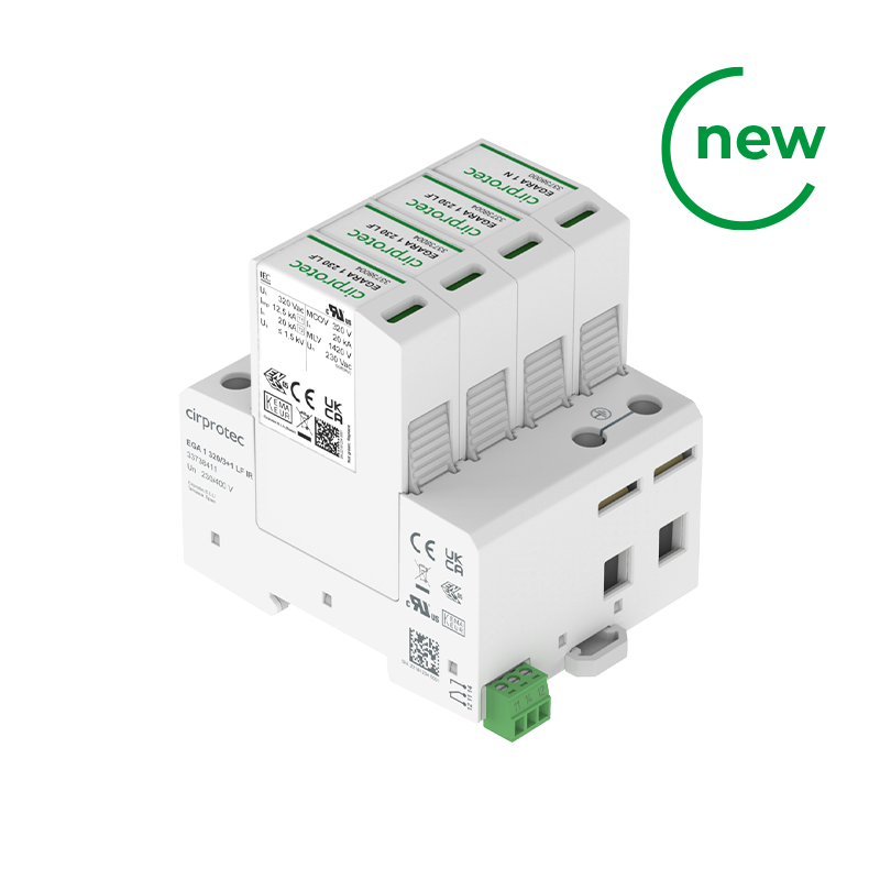
Sobretensiones transitorias Tipo 1+2 en centralizaciones de contadores y aplicaciones industriales exigentes. Libre de corrientes de fuga.
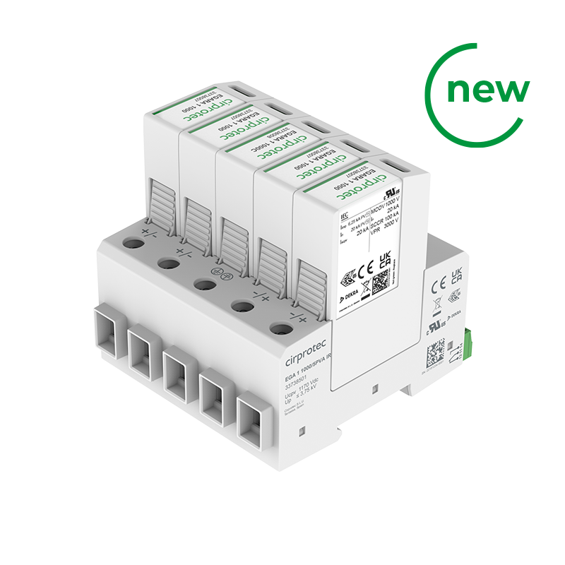
Sobretensiones transitorias PV Tipo 1+2 en formato multi-polo para protección de 2 o 3 MPPT. Eficiencia en coste, espacio y cableado.
Protector DPS + POP con deslastre y rearme automático por corte contador. Impedancia infinita. Esquema 2 ITC-BT 52.
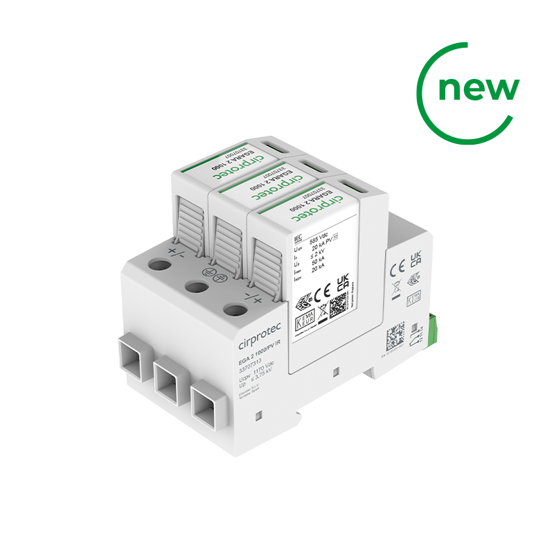
Sobretensiones transitorias PV Tipo 2. Multi-certificado IEC/EN, UL. Calidad y seguridad en fotovoltaica (PV) y almacenamiento (BESS).
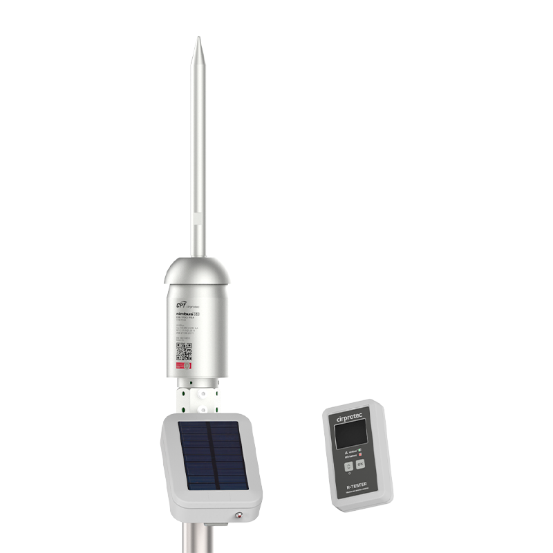
Pararrayos PDC/ESE con tecnología de verificación a distancia. Mantenimiento periódico fácil en instalaciones de difícil acceso.
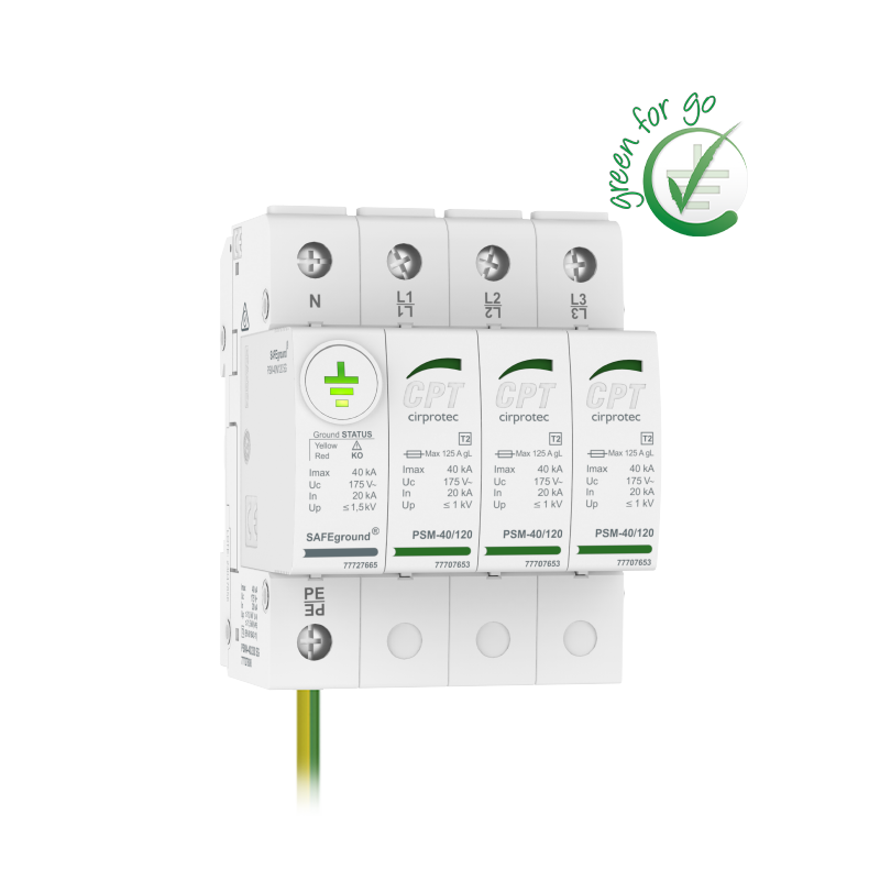
Monitorización de la puesta a tierra dentro del propio protector DPS Tipo 2. Sin tierra no hay protección. Patente mundial.
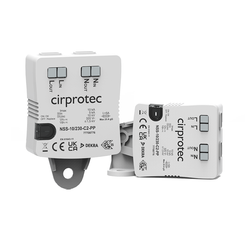
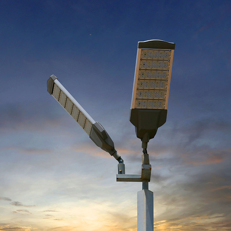
Sobretensiones transitorias Tipo 2+3 para drivers de luminarias de alumbrado exterior LED. Cableado Push-in fácil. Certificado ENEC.
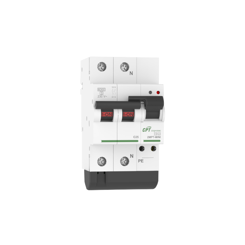
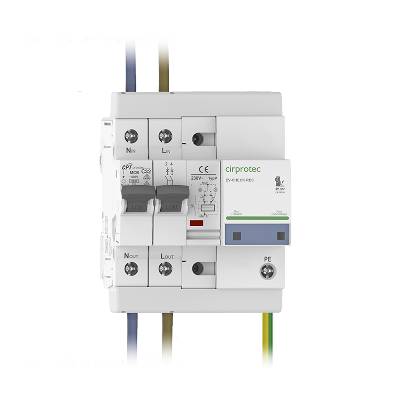
Protector combinado sobretensiones transitorias y permanentes, con IGA. Compacto y precableado. Botón de test e indicación POP.